Adding a power button and status LEDs to you Raspberry Pi
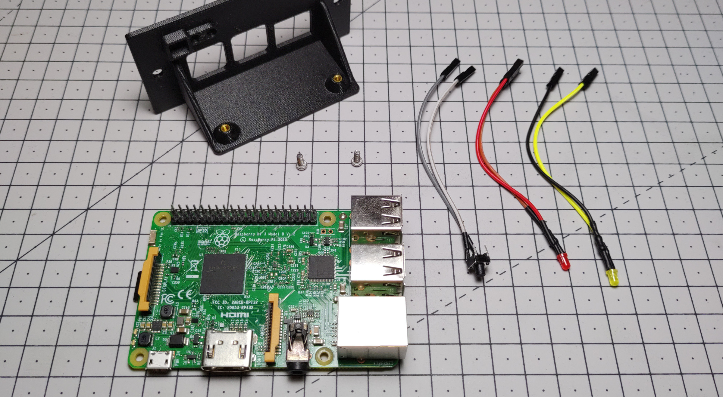
Following the release of my MP-1 Rack collection, I wanted to share some more details about how I added a power button, a power status LED, and an activity LED to my Raspberry Pi module.
Finding the right configuration was not as easy as it seems, and as I wasn’t able to find a single source where both a power button and some status LED were added together, I ended up testing quite a lot of different setup. The ultimate goal being to be able to handle as much as possible without using important buses, having to solder extra pins or requiring any software on the Pi itself.
Adding a power button
Adding a power button to my Raspberry Pi was relatively straight forward once I understood how the gpio-shutdown overlay worked and which pin to use to restart the Pi once it was powered off.
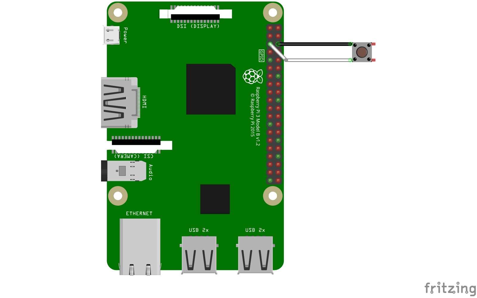
The important part here is to know that, starting with the Raspberry Pi 1 B+, you can restart a powered off board by bridging the GPIO3 pin (Pin 5) to Ground. By knowing that, we can also configure the gpio-shutdown overlay to use this same pin to cleanly shut down a Raspberry Pi when it’s on.
So, in order to add a power button to my Pi, I connected a momentary push button between those two pins as follows:
Then update the /boot/config.txt file to include the following:
dtoverlay=gpio-shutdown,gpio_pin=3,debounce=1000
This configures the gpio-shutdown overlay to use the GPIO3 pin for shutdown with a debounce value of 1000 ms (1 second) meaning that the button needs to be pressed for at least 1s before the Pi starts its shutdown procedure. This parameter is pretty useful to prevent accidental triggering.
The only issue with using this setup to handle power management is that the GPIO3 pin is also used by the I²C bus as the SCL Pin thus requiring I²C to be disabled. If this bus is required, a more complex setup might be possible but has not been investigated here.
Note
Using
gpio-shutdownto power off a Raspberry Pi does not completely cut power to it, it only puts it in a halted state (similar to what happens when runningpowerofforhalton it). It will still consume a negligible amount of power.
Adding a power status LED
Things started to get a little harder once I tried to add a power status LED. A lot of different setup have been documented on the internet such as wiring it to the UART TXD pin, but I felt like using the UART bus this way wasn’t a clean solution.
Another issue I found was most of the setup were using pins that are pulled up to 3.3V when the Pi is powered off (pin 1 to 8 are pulled up by default, requiring a pull-down resistor to be used properly). This can be a nice side effect if you wish to have a dimmed LED when the Raspberry Pi is powered off, but this wasn’t what I was looking for.
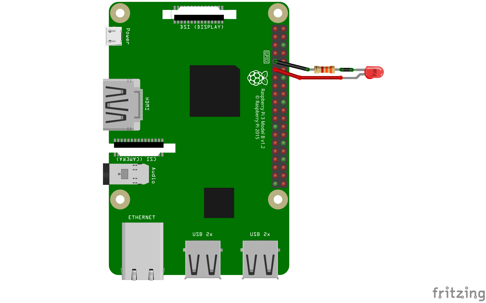
In the end I decided to use the GPIO17 pin (Pin 11) with the GPIO control directives available in config.txt to drive it high on boot. As this pin is not pulled-up by default, the LED will be completely off when the Pi is off.
Using a 3 mm 2.2V 20mA red LED with a 3.3 kΩ resistor (to reduce its brightness), I installed it between GPIO17 and Ground as follows:
Then updated the /boot/config.txt file to add the following directive with instruct the system to drive the GPIO17 pin high on boot:
gpio=17=op,dh
This setup can be adapted to any other GPIO pin available on the board with the caveat about pulled-up pins previously described. A pretty neat setup I tested “abusing” this caveat was to use the GPIO2 pin using gpio=2=op,dh to have a dimly lit LED when the Pi is off and a brighter LED when it’s on.
Adding an activity LED
Finally, it was time to add an external activity LED, this was pretty easy once I stumbled upon the act-led overlay. This overlay is easy to configure as it only really requires a GPIO pin but can be customized using the act_led_trigger parameter to choose which event should trigger it.
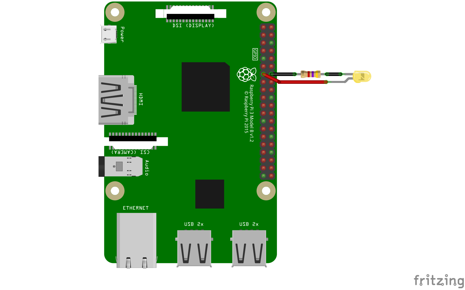
The choice of the GPIO pin to use had to follow the same logic as for the power status LED, but I really couldn’t use a pulled-up pin here as I didn’t want it to light up at all if nothing happened on the Pi. In the end I decided to use the GPIO27 pin (Pin 13) as it was near a ground pin, close to GPIO17 and not pulled-up by default.
Here I used a 3 mm 2.2V 20mA yellow LED with a 4.7 kΩ resistor (still to limit its brightness) wired between GPIO27 and Ground:
Finally, updating the /boot/config.txt one last time to add act-led overlay configuration:
dtparam=act_led_trigger=mmc0
dtoverlay=act-led,activelow=off,gpio=27
Here I set the act_led_trigger to mmc0 which will make the LED react to filesystem usage on the SD card of the Pi. This could be set to any of the other triggers available from the following list:
none                No trigger
kbd-scrolllock      Keyboard scroll lock
kbd-numlock         Keyboard num lock
kbd-capslock        Keyboard caps lock
kbd-kanalock        Keyboard kana lock
kbd-shiftlock       Keyboard shift
kbd-altgrlock       Keyboard altgr
kbd-ctrllock        Keyboard ctrl
kbd-altlock         Keyboard alt
kbd-shiftllock      Keyboard left shift
kbd-shiftrlock      Keyboard right shift
kbd-ctrlllock       Keyboard left ctrl
kbd-ctrlrlock       Keyboard right ctrl
timer               Flash at 1 second intervals
oneshot             Flash only once
heartbeat           Flash like a heartbeat (1-0-1-00000)
backlight           Always on
gpio                Flash when a certain GPIO is high???
cpu0                Flash on cpu0 usage
cpu1                Flash on cpu1 usage
cpu2                Flash on cpu2 usage
cpu3                Flash on cpu3 usage
default-on          Always on
[input]             Default state
panic               Flash on kernel panic
mmc0                Flash on mmc0 (primary SD Card interface) activity
mmc1                Flash on mmc1 (secondary SD Card interface) activity
rfkill0             Flash on wifi activity
rfkill1             Flash on bluetooth activity
Thanks to Ameer on the Raspberry Pi Stack Exchange forum for creating this list.
Final setup
In the end, if we put everything together we can achieve quite a nice setup without requiring any extra software on your Raspberry Pi that handles:
- a power button to shut down and reboot your Raspberry Pi
- a power status LED lighting up when the system if on
- an activity LED reacting to file system
The final wiring diagram should look like this:
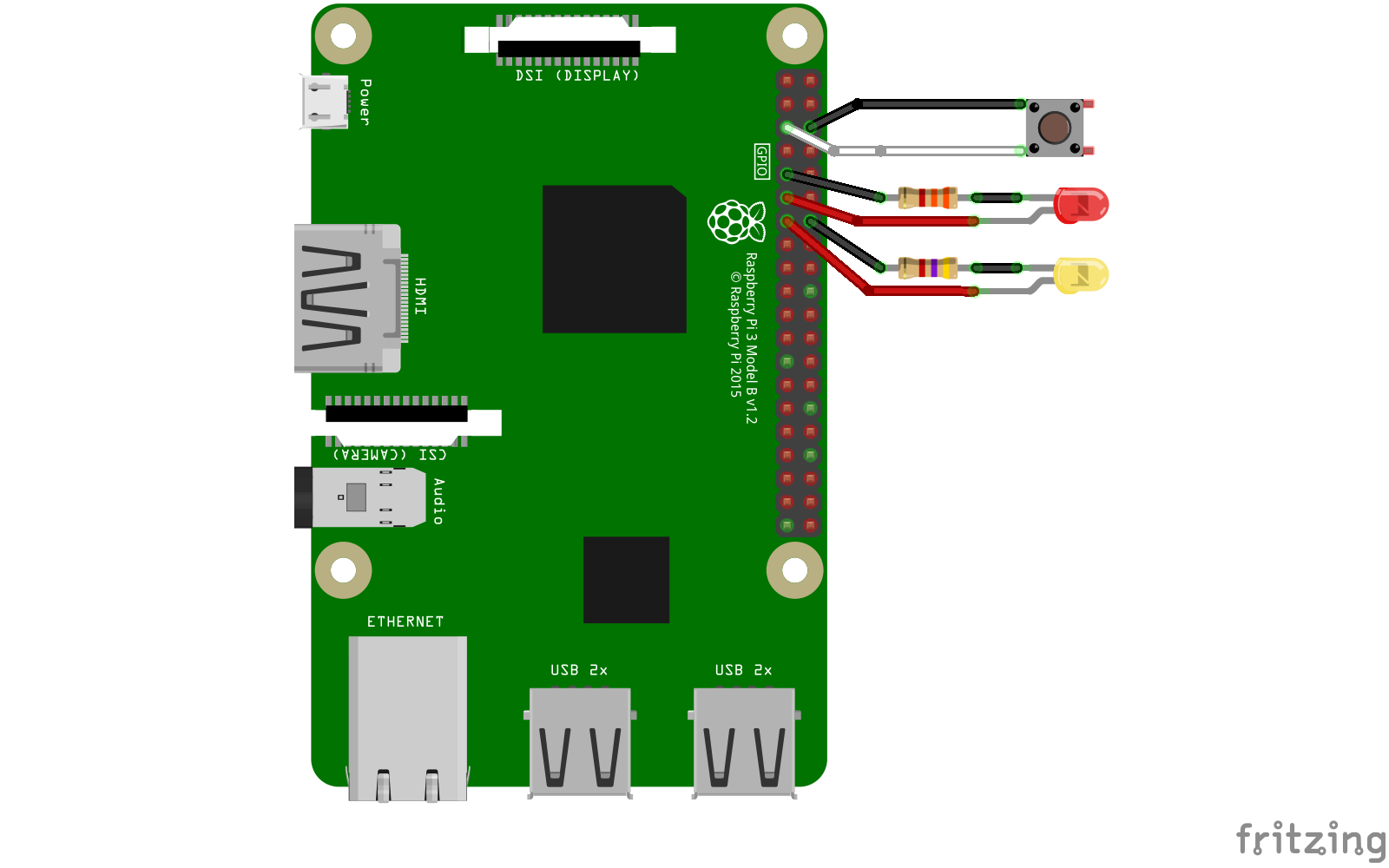
And the /boot/config.txt file should have the following lines at the end:
# Power button
dtoverlay=gpio-shutdown,gpio_pin=3,debounce=1000

# Power status LED
gpio=17=op,dh

# Activity LED
dtparam=act_led_trigger=mmc0
dtoverlay=act-led,activelow=off,gpio=27
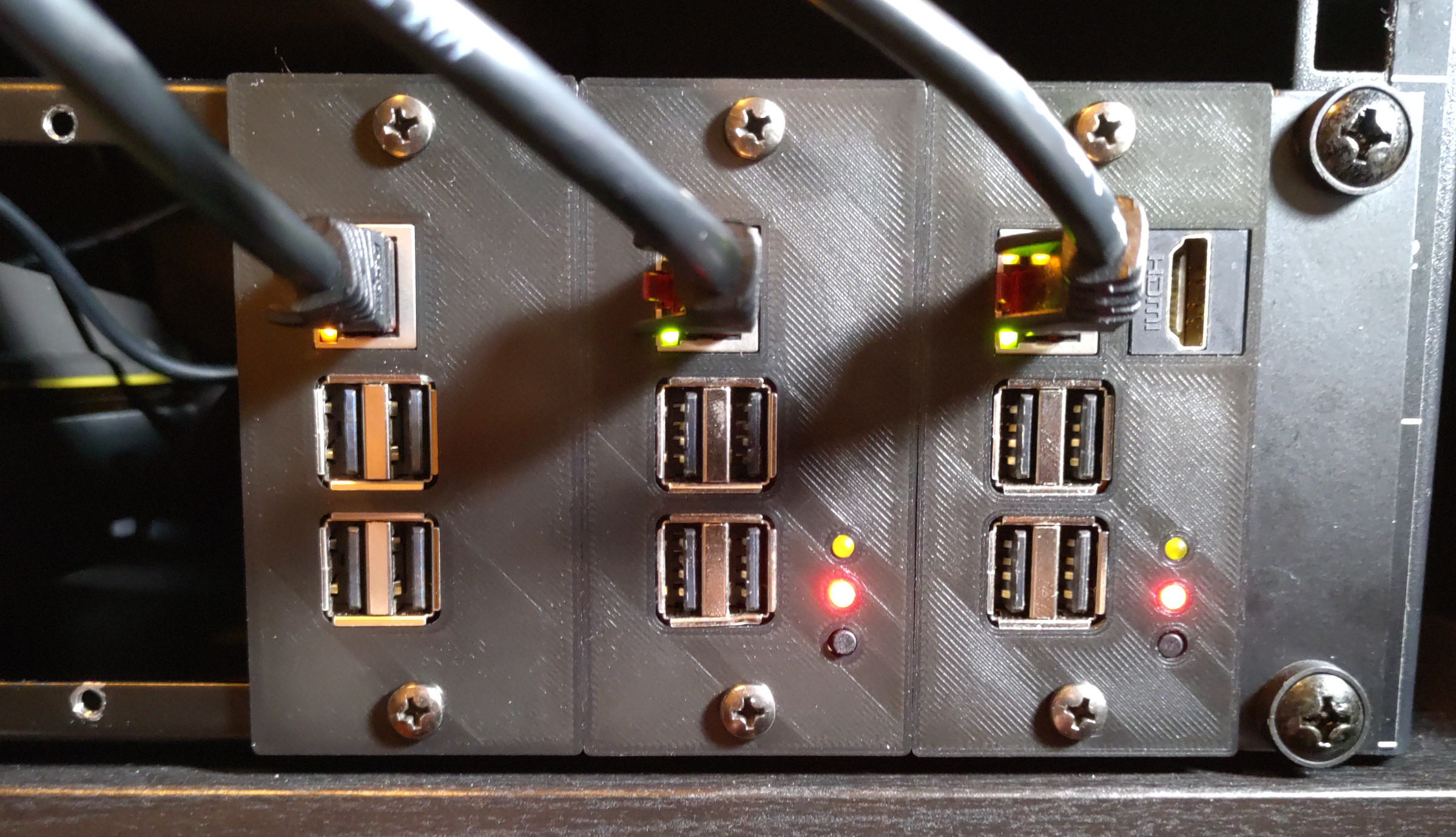
Paired with the MP-1 Rack Raspberry Pi module, this setup allowed me to achieve my goal of having a rack mounted solution with power controls and feedback for my Pis. And I hope it helped you too if you were looking for something similar
References
gpio-shutdownoverlay documentation- Raspberry Pi Power-Up and Shutdown with a Physical Button by Jeremy S. Cook
- Raspberry pi powerdown and powerup button by Matthijs Kooijman
- Build a Simple Raspberry Pi LED Power/Status Indicator by Zach on Howchoo
- Use GPIO 2 for power LED on the Raspberry Pi forum
- External PWR & ACT LEDS on the Raspberry Pi forum
act_led_triggervalues by Ameer on StackExchange